#basics of i2c protocol
Explore tagged Tumblr posts
Visit Tumblr Blog
Explore Tumblr blogs with no restrictions, modern design and the best experience.
Last Seen Tumblr Blogs


Fun Fact
Tumblr was named as a finalist in Lead411’s New York City Hot 125 in Aug 2010.
Text
How i2C protocol works....
#mobicationhub #mobicationhub9509959090 #Protocol #reelsfypシ #i2c #institute #phonerepair #mobilerepaircoursejaipur #mobilerepairing #working #1monthcours #laptop
#i2c protocol#i2c protocol tutorial#protocol#spi protocol#communication protocols#i2c protocol vs spi protocol#communication protocol#how i2c protocol works#i2c protocol - inter integrated circuit protocol#i2c communication protocol#i2c protocol working#serial communication protocol#inter integrated circuit protocol#inter-integrated circuit protocol#i2c bus protocol#i3c protocol#what is i2c protocol#basics of i2c protocol#spi protocol tutorial
0 notes
Note
WARNING: LONG ASK INCOMING
For hobby electronics there’s two major kinds of processors: Microcomputers and Microcontrollers. Microcomputers are small full computer systems like the Raspberry Pi, they typically run a general-purpose OS (typically some flavor of Linux) and are useful for the kinds of projects that require basically a full computer to function, but not necessarily individual sensors. They’re a great place to start for people who don’t know a whole ton about programming or working with individual components because they typically can output a true GUI to a screen and have the capabilities of a regular desktop computer. They have a main processor, true RAM, and either large on-board storage space or a way to read a storage device, like an SD card.
Microcontrollers are less complicated (component wise) than microcomputers, but as a result are more difficult for total beginners to begin working with. They’re typically primarily a SoC (System on a Chip) processor without discrete RAM modules and a very small EEPROM (on-ship storage space) and need to have components wired and configured to them to be able to do much more than being a fancy calculator. They’re used for when you need something to carry out electronic functions or get sensor readings, but not necessarily a full operating system, so they’re best suited for small/integrated applications. Your helmet uses a microcontroller to control the LEDs you used in the Cunt Machine post.
I build high-power model rockets as a hobby and with my university team, so I work with both kinds of processor as part of designing payload systems. I typically prefer microcontrollers in these as most of what we do doesn’t need an actual OS to run, and they’re smaller/lighter than microcomputers. One of the advantages of a microcontroller is that it runs a Real-Time OS (RTOS) which forgoes all the user-friendliness of things like windows and linux to instead be the bare minimum backend necessary to run code uploaded into the processor.
The main advantage of using a microcontroller is really that they’re typically a lot cheaper than microcomputers are and are plenty powerful for really embedded applications. They also make other parts of whatever system is being built cheaper/easier to integrate because they require less overhead to function - the raspberry pi needs a minimum of 5 volts of power to work, while a chip like an ESP32-PICO can run at 1.8V.
The main way you make sensors/buttons/peripherals work with a microcontroller is via digital communication busses. There’s a few protocols, the most common being I2C, SPI, and UART. I’ll talk about I2C since that’s generally the most common. With I2C each component is assigned a 2-byte “address” that they’re identified by. When the controller sends a request signal on the I2C data bus, every sensor along the line will return their own signal, marked with their address so that they can be identified. It allows for a large number of devices to be put on the same lines and you can daisy-chain them through each other to the microcontroller.
I’ll be honest I really can’t think of a good way to say much more on the subject as like a starting message because I’ve been working with computers so long all the tech stuff for me is second nature, but if you have any questions ask away I can probably answer them or google them.
.
#AAAAAAAAAAAAAAAAAAAA TY INFORMATION#no yeah this is either really beginner friendly or. friendly to how much i have learned so far#tysm!!!! your insight is consistently so helpful <3#ask#lobsterbitches
27 notes
·
View notes
Text
Embedded Systems Course Online – Learn with Technoscripts
Embedded systems are the silent force behind many of the machines & devices we rely on every day. From a simple digital watch to complex automotive control units, embedded systems are quietly doing their job. With the world becoming more tech-driven, learning embedded systems is no longer just an option, it's a necessity for those aiming to work in core electronics & automation.
Technoscripts has created an online embedded systems course tailored for learners who want to build skills from scratch or enhance what they already know. The course is structured with a balance of core theory & hands-on experience, aiming to develop practical skills that actually work in real-world applications.
Why Learn Embedded Systems?
Everywhere you look in industries, homes, vehicles there’s some form of embedded technology at work. These systems are built to carry out specific tasks efficiently. Unlike general-purpose computers, they’re programmed to do one job, & do it well.
Industries such as automotive, telecommunications, healthcare, robotics, & agriculture are using embedded systems in their daily operations. These industries grow, so does the need for professionals who can design, program, & maintain such advanced embedded systems & technologies. If you understand how these small computers operate within machines, you open up a wide range of job and placement opportunities across various sectors.
What This Course Offers
This course is built for learners at all levels. Whether you’re a student from an engineering background or a working professional looking to switch fields, you’ll find the modules easy to follow yet detailed enough to build real skills with our embedded systems course online.
The course includes:
Programming with microcontrollers like 8051, PIC, & ARM
Basics of embedded C & real-time operating systems
Sensor & peripheral interfacing
Understanding & using communication protocols like UART, I2C, SPI
Debugging techniques & h&s-on project development
Each module is created for practical exercises so learners don’t just understand the theory they apply it for industrial use.
Flexible Learning, Expert Guidance
One of the biggest advantages of our course is flexibility. You can attend classes from anywhere, revisit recorded lectures anytime, & ask questions during live sessions. Our trainers are experienced engineers with actual industry exposure. This ensures that you are not just learning concepts but also how they’re used in professional life and career in future.
Who Can Join?
This program is ideal for:
Final-year engineering students
Diploma holders in electronics or related fields
Professionals in IT or electronics wanting to upskill
Anyone interested in electronics & embedded technology
What You’ll Walk Away With
After completing the course, you’ll be able to build embedded projects on your own, & understand how various components work together, & write programs that run on microcontrollers. You’ll also receive a certificate, project experience, & most importantly, the skills that companies actually look for.
Technoscripts also offers placement support for eligible candidates through a dedicated placement cell that connects you with hiring companies in embedded development & R&D roles.
Why Choose Technoscripts?
Courses shaped by real industry needs
Live project work during training
Personal mentorship & doubt-solving
Flexible class timings for working professionals
Certification & job assistance after course completion
Start Learning Today
If embedded systems excite you, & you’re ready to begin your learning journey, now is the time. With Technoscripts’ online embedded systems course, you don’t need to be in a classroom to gain valuable knowledge, you just need the right platform.
For more details or to enroll, visit our website or connect with our admissions team today.
0 notes
Text
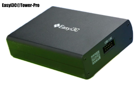
【step by step】Easyi3C Host I3C adapter (1)
Easyi3C is a leading supplier of embedded system tools that simplify the development and debugging of various communication protocols. The company offers a range of products designed to help engineers and developers use I3C/I2C , USB and MIPI, JEDEC, MCTP and other protocols more efficiently.
1. Basic Introduction
Easyi3C Host I3C adapter is a powerful and easy-to-use I3C and I2C host adapter produced by Easyi3C. It connects the computer to the downstream embedded system environment through the USB interface and adopts the advanced I3C and I2C protocol.
Based on the application programming interface (API) function and the Easyi3C Tower console graphical user interface (GUI) tool, combined with the Python development environment, the Easyi3C Host adapter greatly simplifies the development process of I3C/I2C chip testing and data transmission environment. It provides great convenience for AE engineers, FAE engineers, etc. to verify I3C/I2C chips. Simple verification can be done through the graphical console interface, which is easy to use and easy to learn. If you want to test more complex functions or perform automated testing, you can use the rich API functions provided by the manufacturer to quickly implement automated scripts in the Python development environment.
We know that I2C was invented by Philips Semiconductors in 1981, and its history is a bit old and mature. The I3C protocol I3C specification was originally released by in 2017. I3C is the abbreviation of improved internal integrated circuit, which is a 2-wire digital interface similar to I2C. It improves and optimizes the previously released I2C and SPI interfaces, solves the problem of slow I2C communication speed, and optimizes the shortcomings of SPI through four-wire connection. The I3C specification is managed by MIPI Alliance Inc. I3C also solves the problem of high power consumption of I2C. I3C becomes a low-power, low-cost and fast digital interface. It supports multi-point connection between host MCU and peripheral devices such as sensors and multi-master devices. Because the protocol is still very new, there are not many good tools on the market. The series of products launched by Easyi3C will fill this gap. The same interface supports I3C/I2C protocols at the same time, which is convenient for engineers to write automated scripts for chip protocol testing, shorten the product launch cycle, and help the company’s products win the competition.
2. Key features:
Supports MIPI I3C BASIC v1.1 JEDEC JESD403–1 Specifications (JEDEC DDR5 Sideband Bus Spec) I3C Master in SDR mode Variable Working Frequencies (Open-Drain Mode: 1 kHz to 4 MHz (Default: 1MHz); Push-Pull Mode: 100KHz to 12.5 MHz (Default: 4MHz)) Adjustable SCL Duty Cycle Amplitude Variation: 0.8V to 3.3V in steps of 10mV 5ns resolution Supports 7-Bit Slave Addressing Supports Common Command Code (CCC) transactions Supports flexible payload length’s IBI Supports Hot Plug Supports all Dynamic Address Assignments Supports legacy I2C Master, Software configurable I2C pull-up Error Injection such as parity errors USB Type-C port, Max. Current & Voltage: 500 mA @ 5 V Supports online upgrade API support for automation test in Python Physical Size: 114mm x 81mm x 27mm Operating Temperature From –20°C to +85°C
3. Hardware
Accessories:


4. Interface Introduction 4.1 Front Panel


5. Test chip connection method
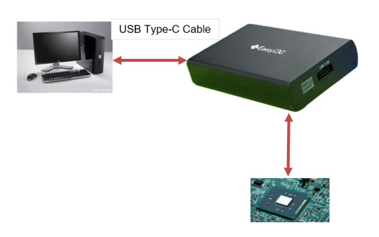
5.1 Connect the Easyi3C adapter to the I2C/I3C device using a 10-pin cable.
5.2 Connect the Easyi3C adapter to the computer with a USB Type-C cable. The adapter is powered by USB Type-C communication, so no separate external power supply is required, which simplifies device connection.
Next, we will continue to introduce the use of the product in depth.
1 note
·
View note
Text
raspberry pi pc
Yes, a Raspberry Pi would indeed work much better than an Arduino for implementing a system where two "computers" are communicating and learning from each other. The Raspberry Pi is a full-fledged single-board computer (SBC), which means it has far greater processing power, memory, and capabilities compared to an Arduino. This makes it much more suitable for complex tasks like data processing, machine learning, and communication between two devices.
Key Differences Between Arduino and Raspberry Pi for This Task:
1. Processing Power:
Arduino: Limited to simple microcontroller tasks (e.g., simple sensors, I/O operations, small control tasks). It has very little computational power and memory (e.g., 2 KB of RAM, 32 KB of flash memory).
Raspberry Pi: Has a powerful CPU, much more memory (e.g., 4 GB or 8 GB of RAM on newer models), and can run a full Linux-based operating system (e.g., Raspberry Pi OS). This makes it suitable for tasks like running machine learning models, more complex algorithms, and networking tasks.
2. Communication:
Arduino: Can communicate using simple protocols like Serial, I2C, or SPI, which are ideal for small-scale, low-speed communication between devices.
Raspberry Pi: Has multiple communication options including Ethernet, Wi-Fi, and Bluetooth, along with more advanced serial protocols. It can communicate over a local network or even the internet, making it ideal for real-time communication between two "computers."
3. Storage and Software:
Arduino: Does not have a storage system other than its limited onboard memory (though you can use SD cards for small amounts of storage). The code running on an Arduino is typically bare-metal (no operating system), and it can only run a single program at a time.
Raspberry Pi: Has access to a large amount of storage (via microSD card or external storage), and runs a full operating system, allowing you to install software libraries, run multiple processes simultaneously, and use advanced tools and frameworks for communication and learning (e.g., TensorFlow, OpenCV, etc.).
4. Machine Learning and Data Processing:
Arduino: You can implement simple algorithms (like decision trees or basic pattern recognition), but it’s not suited for real-time machine learning or complex data analysis.
Raspberry Pi: Can run machine learning models, handle large datasets, and run frameworks like TensorFlow, PyTorch, scikit-learn, etc. This makes it much more capable of "learning" from data, making decisions, and adapting based on feedback.
5. How a Raspberry Pi PC System Could Work Better
Given that Raspberry Pi is a full-fledged computer, you can implement the original idea of two computers communicating and learning from each other in a much more robust way. Here’s how you can achieve that:
Hardware Setup for Raspberry Pi PCs:
Two Raspberry Pi boards (e.g., Raspberry Pi 4, Raspberry Pi 3, or even Raspberry Pi Zero for smaller setups).
Display, keyboard, and mouse for local interaction, or run everything remotely via SSH (headless).
Networking: Use Wi-Fi or Ethernet to connect the two Raspberry Pi boards and enable communication.
Optional: Camera, microphone, sensors, or other input/output devices for more advanced interaction and learning tasks.
Communication Between Raspberry Pi PCs:
You can use several methods for communication between the two Raspberry Pi boards:
TCP/IP Communication: Set up a client-server model, where one Raspberry Pi acts as the server and the other as the client. They can communicate over a local network using sockets.
MQTT: A lightweight messaging protocol suitable for device-to-device communication, commonly used in IoT.
HTTP/REST APIs: You can use a web framework (e.g., Flask, FastAPI) to create APIs on each Raspberry Pi, allowing them to communicate via HTTP requests and responses.
WebSocket: For real-time bidirectional communication, you can use WebSockets.
Software/Frameworks for Machine Learning:
You can install frameworks like TensorFlow, Keras, or scikit-learn on the Raspberry Pi to allow for more advanced learning tasks.
Use Python as the programming language to communicate between the two Pi boards and implement machine learning algorithms.
Raspberry Pi can interact with real-world data (e.g., sensors, cameras, etc.) and learn from it by running algorithms like reinforcement learning, supervised learning, or unsupervised learning.
6. Example Use Case: Two Raspberry Pi PCs Learning from Each Other
Here’s an example scenario where two Raspberry Pi boards communicate and learn from each other using TCP/IP communication and basic machine learning (e.g., reinforcement learning).
Raspberry Pi 1 (PC1): This board makes a decision based on its current state (e.g., it guesses a number or makes a recommendation).
Raspberry Pi 2 (PC2): This board evaluates the decision made by PC1 and sends feedback. PC2 might "reward" or "punish" PC1 based on whether the decision was correct (e.g., in a game or optimization problem).
Feedback Loop: PC1 uses the feedback from PC2 to adjust its behavior and improve its future decisions.
Example Architecture:
PC1 (Raspberry Pi 1):
Makes a guess (e.g., guesses a number or makes a recommendation).
Sends the guess to PC2 via TCP/IP.
Receives feedback from PC2 about the quality of the guess.
Updates its model/behavior based on the feedback.
PC2 (Raspberry Pi 2):
Receives the guess or recommendation from PC1.
Evaluates the guess (e.g., checks if it’s close to the correct answer).
Sends feedback to PC1 (e.g., positive or negative reinforcement).
Basic Python Code for TCP Communication:
On both Raspberry Pis, you can use Python’s socket library to establish a client-server communication:
PC1 (Server) Code:
import socket import random # Create a TCP/IP socket server_socket = socket.socket(socket.AF_INET, socket.SOCK_STREAM) server_socket.bind(('0.0.0.0', 65432)) # Bind to any address, port 65432 server_socket.listen(1) print("PC1: Waiting for connection...") connection, client_address = server_socket.accept() print("PC1: Connected to PC2") while True: # Simulate a decision (e.g., guessing a number) guess = random.randint(1, 100) print(f"PC1: Guessing number {guess}") # Send the guess to PC2 connection.sendall(str(guess).encode()) # Wait for feedback from PC2 feedback = connection.recv(1024).decode() print(f"PC1: Received feedback: {feedback}") # Adjust behavior based on feedback (simple learning mechanism) if feedback == "correct": print("PC1: Correct guess!") else: print("PC1: Incorrect guess, trying again.") # Wait before making another guess time.sleep(2)
PC2 (Client) Code:
import socket # Create a TCP/IP socket client_socket = socket.socket(socket.AF_INET, socket.SOCK_STREAM) client_socket.connect(('PC1_IP_ADDRESS', 65432)) # Connect to PC1 while True: # Receive the guess from PC1 guess = int(client_socket.recv(1024).decode()) print(f"PC2: Received guess {guess}") # Evaluate the guess (simple decision: correct if guess is 50) if guess == 50: feedback = "correct" else: feedback = "incorrect" # Send feedback to PC1 client_socket.sendall(feedback.encode()) print(f"PC2: Sent feedback: {feedback}")
7. Expanding This System
Advanced Communication: If you're looking for real-time interaction, you can explore using WebSockets or MQTT for more efficient, bidirectional communication.
Machine Learning: You can train models on both Raspberry Pi devices, where one device sends data to the other for training, and they both improve over time.
Distributed Systems: With two Raspberry Pis, you can build a distributed system where each Pi runs part of the computation, and they collaborate to solve more complex tasks.
Conclusion:
Raspberry Pi is definitely a better choice for the task of two computers communicating and learning from each other, as it offers the computational power, memory, and flexibility needed for machine learning, real-time communication, and more advanced systems. The Arduino is more suitable for simple tasks and small embedded systems, whereas the Raspberry Pi can handle much more complex processing, communication, and learning systems.
If you want to build a more advanced learning system, I would recommend using Raspberry Pi boards. Would you like to dive deeper into a specific part of the setup or need help with more advanced machine learning on Raspberry Pi?
Creating a Raspberry Pi-based PC involves setting up a Raspberry Pi board to function as a full desktop computer, capable of running an operating system, connecting to the internet, and supporting peripherals like a keyboard, mouse, and display. Unlike an Arduino, which is used for embedded systems, a Raspberry Pi is a full-fledged computer, making it much easier to set up as a personal computer.
Here’s a step-by-step guide on how to turn a Raspberry Pi into a fully functional PC.
What You Need:
Raspberry Pi Board (e.g., Raspberry Pi 4, Raspberry Pi 3, or Raspberry Pi Zero)
MicroSD Card (at least 8 GB, recommended 16 GB or more) for the operating system
Power Supply (5V 3A USB-C for Raspberry Pi 4, or appropriate power for other models)
HDMI Cable and a Display (HDMI-compatible monitor or TV)
Keyboard and Mouse (USB or Bluetooth, depending on your preference)
Internet connection (Ethernet cable or Wi-Fi)
USB storage (optional, for additional storage)
MicroSD card reader (for flashing the operating system)
Step-by-Step Guide:
1. Prepare the MicroSD Card with Raspberry Pi OS
First, you'll need to install the operating system on your MicroSD card. The most common and recommended OS for Raspberry Pi is Raspberry Pi OS (formerly Raspbian).
Download Raspberry Pi Imager: Visit Raspberry Pi’s official website and download the Raspberry Pi Imager for your computer (Windows, macOS, or Linux).
Install Raspberry Pi OS:
Open the Raspberry Pi Imager, select "Choose OS", and select Raspberry Pi OS (32-bit) (recommended for most users).
Select your MicroSD card as the target.
Click Write to flash the OS onto the SD card.
Enable SSH or Wi-Fi (Optional): If you plan to use the Raspberry Pi headlessly (without a monitor, keyboard, or mouse), you can enable SSH or configure Wi-Fi before inserting the SD card into the Pi:
After flashing, insert the SD card into your computer.
Open the boot partition and create an empty file named "ssh" (no extension) to enable SSH.
For Wi-Fi, create a file called wpa_supplicant.conf with your Wi-Fi credentials: country=US ctrl_interface=DIR=/var/run/wpa_supplicant GROUP=netdev update_config=1 network={ ssid="Your_SSID" psk="Your_Password" }
2. Set Up the Raspberry Pi
Insert the SD card into the Raspberry Pi.
Connect your HDMI cable from the Raspberry Pi to the monitor.
Plug in your keyboard and mouse via the USB ports.
Connect the power supply to the Raspberry Pi.
3. First Boot and Raspberry Pi OS Setup
When you power on the Raspberry Pi, it should boot into Raspberry Pi OS.
Follow the on-screen instructions to:
Set up your language, timezone, and keyboard layout.
Set up your Wi-Fi connection (if not already done).
Update the system by running sudo apt update and sudo apt upgrade in the terminal.
4. Install Additional Software
Once your Raspberry Pi is running, you can install additional software based on your needs. For example:
Web Browsing: The default browser is Chromium, but you can install others like Firefox.
Office Suite: Install LibreOffice for document editing, spreadsheets, and presentations.
Command: sudo apt install libreoffice
Development Tools: If you want to use the Pi for programming, you can install IDEs like Thonny (for Python) or Visual Studio Code.
Command: sudo apt install code
Media Software: You can use VLC for media playback or Kodi for a home theater system.
5. Optimize Your Setup
To make your Raspberry Pi run smoothly and feel more like a desktop PC:
Increase Memory Allocation: If you're using a Raspberry Pi 4, you can allocate more memory to the GPU via sudo raspi-config.
Enable Auto-Login: To skip the login screen on boot, you can configure auto-login:
Run sudo raspi-config.
Select Boot Options → Desktop/CLI → Desktop Autologin.
Configure Performance Settings: You can tweak performance settings like CPU overclocking or enabling hardware acceleration for graphics in the Raspberry Pi configuration tool (raspi-config).
6. Optional: Adding a Large Storage Device
If the 8 GB or 16 GB of storage on the SD card isn’t enough, you can plug in a USB hard drive or USB flash drive to expand your storage. You can also configure the Raspberry Pi to boot from a USB drive (for faster performance compared to an SD card).
7. Set Up Remote Access (Optional)
If you prefer to control the Raspberry Pi from another computer:
SSH: You can access the Raspberry Pi's terminal remotely via SSH (if enabled during setup). To connect, use a tool like PuTTY (Windows) or the terminal (Linux/macOS):
Command: ssh pi@<raspberrypi-ip-address>
VNC: You can use VNC for remote desktop access.
Enable VNC using sudo raspi-config.
Download and install RealVNC on your computer to access the Raspberry Pi’s graphical desktop remotely.
8. Using Your Raspberry Pi as a Full PC
Once you’ve completed the setup, your Raspberry Pi will be ready to use like a regular desktop computer. You can:
Surf the web, check emails, and use social media with browsers like Chromium or Firefox.
Write documents, create spreadsheets, and presentations using LibreOffice.
Code in multiple languages (Python, Java, C++, etc.).
Play media files with VLC or stream content using Kodi.
9. Advanced Uses: Building a Raspberry Pi "Server"
If you want your Raspberry Pi to act as a server or take on additional tasks, you can configure it for various roles:
Home Automation: Set up a Home Assistant or OpenHAB server for smart home automation.
Web Server: You can install Apache or Nginx and run a web server.
Command: sudo apt install apache2
Cloud Server: Set up Nextcloud or ownCloud to create your own cloud storage.
Conclusion
Creating a Raspberry Pi PC is a great way to repurpose the Raspberry Pi as a low-cost, energy-efficient desktop computer. Whether you're using it for everyday tasks like browsing, programming, or media consumption, or even more advanced tasks like running servers or learning about Linux, the Raspberry Pi is incredibly versatile.
If you need help with specific configurations, software installation, or troubleshooting, feel free to ask!
0 notes
Text
Emertxe Embedded Systems Online Course – A Gateway to a Thriving Career
Are you looking to kickstart your career in embedded systems but don't have the time to attend traditional classroom-based courses? Emertxe's Embedded Systems Online Course offers the perfect solution to gain in-depth knowledge and practical experience in this rapidly growing field from the comfort of your home.
Why Choose Emertxe’s Embedded Systems Online Course?
Emertxe is a leading provider of embedded systems training, offering specialized online courses designed to bridge the gap between academic knowledge and industry requirements. With its embedded systems online program, you can gain expertise in key areas such as microcontrollers, real-time operating systems (RTOS), device drivers, communication protocols, and much more.
Here’s why Emertxe’s embedded systems online course stands out:
1. Industry-Recognized Curriculum
Emertxe’s course content is developed in collaboration with industry experts and aligned with the latest trends and technologies in embedded systems. The online embedded systems program includes everything from the basics to advanced topics, ensuring that you are well-prepared for industry challenges.
2. Hands-on Learning Experience
Emertxe’s online embedded systems course focuses heavily on practical learning. You will work on real-time projects, assignments, and simulations that help solidify your understanding and improve your problem-solving skills. Emertxe’s online platform makes it easy to access tutorials, lab sessions, and code examples anytime, anywhere.
3. Experienced Trainers
Learn from highly qualified instructors who have hands-on experience in embedded systems development. Emertxe’s trainers are industry veterans who share their insights and guide you through the complexities of embedded system design and implementation.
4. Flexible Learning Pace
One of the key advantages of the Emertxe embedded systems online course is the flexibility it offers. You can learn at your own pace, revisit lessons whenever needed, and balance your studies with personal and professional commitments.
5. Job Placement Assistance
Emertxe provides placement assistance to its students. With its strong industry connections and a network of partner companies, Emertxe helps students get placed in top tech companies. Graduates of the online embedded systems program are highly sought after for roles such as Embedded Engineer, Firmware Developer, and Hardware Design Engineer.
Key Topics Covered in Emertxe’s Embedded Systems Online Course
Introduction to Embedded Systems: Learn the fundamentals of embedded systems, including their applications in various industries like automotive, consumer electronics, healthcare, and more.
Microcontroller Programming: Get hands-on experience in programming microcontrollers like ARM and AVR to build embedded solutions.
Real-Time Operating Systems (RTOS): Dive into RTOS concepts such as task scheduling, inter-process communication, and memory management to design responsive embedded systems.
Embedded C and C++ Programming: Master the core languages used in embedded systems programming and develop efficient, resource-constrained applications.
Device Drivers and Communication Protocols: Learn to develop device drivers and implement protocols like UART, SPI, I2C, and CAN to ensure seamless communication between components in embedded systems.
Embedded Linux: Explore the power of Linux in embedded systems and understand how to work with Linux kernel, drivers, and file systems.
Career Opportunities After Completing Emertxe’s Embedded Systems Online Course
Graduating from Emertxe’s embedded systems online program opens the doors to a wide range of career opportunities. The demand for skilled embedded systems professionals is soaring in sectors like automotive, aerospace, telecommunications, and consumer electronics. Emertxe’s curriculum equips you with the expertise needed to take on roles such as:
Embedded Systems Engineer
Firmware Developer
Embedded Software Developer
Hardware Engineer
Embedded Systems Consultant
How to Enroll in Emertxe’s Embedded Systems Online Course
Enrolling in the Emertxe embedded systems online course is simple. Visit the Emertxe website, select the online course option, and follow the easy steps to complete your registration. With flexible payment plans and a dedicated support team, Emertxe ensures that the entire process is smooth and hassle-free.
Final Thoughts
Emertxe's embedded systems online course is the perfect way to build a solid foundation in embedded systems while balancing your existing commitments. With a comprehensive curriculum, hands-on projects, and job placement assistance, Emertxe ensures that you are ready to take on exciting career opportunities in embedded systems development.
Ready to kickstart your career in embedded systems? Visit Emertxe Embedded Systems Online Course and enroll today!
0 notes
Text
Course Title: Embedded Systems Training at Technoscripts
Overview:
The Embedded Systems Training program at Technoscripts is a comprehensive course designed to equip participants with the necessary skills and knowledge to excel in the field of embedded systems. This training covers a wide range of topics, from fundamental concepts to advanced techniques, providing a solid foundation for individuals looking to pursue a career in embedded systems development.
Course Duration:
Total Hours: 3 Months
Prerequisites:
Basic understanding of programming languages (C, C++)
Familiarity with electronics and microcontrollers
Passion for learning and exploring embedded systems
Course Outline:
Introduction to Embedded Systems
Definition and characteristics of embedded systems
Embedded system architecture and components
Applications of embedded systems in various industries
Microcontroller Fundamentals
Overview of microcontrollers and microprocessors
Architecture and features of popular microcontroller families
Programming microcontrollers using C language
Embedded C Programming
Basics of C programming for embedded systems
Data types, operators, and control structures in C
Memory management and optimization techniques
Embedded System Design Principles
Hardware-software co-design considerations
Real-time operating systems (RTOS) for embedded applications
Design methodologies for efficient embedded system development
Peripheral Interfacing
Interfacing sensors, actuators, and displays with microcontrollers
Communication protocols (SPI, I2C, UART) for peripheral interfacing
Hands-on exercises on peripheral communication
Embedded System Development Tools
Integrated Development Environments (IDEs) for embedded programming
Debugging techniques and tools for troubleshooting embedded systems
Simulation software for testing and validation
RTOS Concepts and Implementation
Introduction to real-time operating systems (RTOS)
Task scheduling, synchronization, and communication in RTOS
Practical examples of multitasking in embedded systems
Embedded System Security
Basics of cybersecurity in embedded systems
Secure coding practices for embedded software development
Techniques for securing IoT devices and connected systems
Assessment:
Regular quizzes and assessments to evaluate progress
Practical assignments to apply theoretical knowledge
Final project to showcase skills acquired during the training program
Certification:
Upon successful completion of the Embedded Systems Training at Technoscripts, participants will receive a certificate of completion, recognizing their proficiency in embedded systems design and development.
This detailed course outline provides a structured framework for delivering a comprehensive training program on embedded systems at Technoscripts. It covers essential topics, hands-on exercises, and assessments to ensure participants acquire practical skills and knowledge in this dynamic field. Feel free to customize the content further based on specific learning objectives and audience requirements.

#automotiveembeddedtestingcourse#embeddedcourse#automotiveembeddedinstitute#automotiveembeddedsystemscourse#automotiveembeddedcourse#embeddedsystemscoursepune#embeddedclasses#embeddedtraining#automotiveembeddedclasses#embeddedinstitute
0 notes
Text
Navigating the World of Embedded Systems: A Simple Guide
Embedded systems are the unsung heroes of modern technology, working silently behind the scenes in devices we use every day, from smartphones to washing machines. Understanding the basics of embedded systems, their design development life cycle, and the core concepts of electronics designing can demystify this intricate world.
What is Embedded System?
An embedded system is a specialized computing device designed to perform dedicated functions within a larger system. It is embedded (built-in) as part of a larger product rather than being a standalone computer.
Examples:
Smartphones, washing machines, medical devices, and automotive control systems are common examples.
They range from simple, like a microwave controller, to complex, like the navigation system in a car.
Characteristics:
Typically, they have real-time computing constraints, meaning they must respond within a specific time frame.
Often operate with minimal user intervention, performing predetermined tasks autonomously.
Embedded Design Development Life Cycle:
Requirements Analysis:
Define the purpose and functionality of the embedded system.
Understand user needs and system constraints.
System Design:
Plan the system architecture, hardware, and software components.
Determine communication protocols and interfaces.
Hardware Design:
Develop the physical components of the system, including the microcontroller, sensors, and actuators.
Consider power consumption, size, and environmental conditions.
Software Design:
Write the embedded software that controls the system.
Develop algorithms, implement functionalities, and ensure real-time responsiveness.
Integration and Testing:
Combine hardware and software components.
Test the embedded system for functionality, performance, and reliability.
Deployment:
Install the embedded system into the final product or device.
Ensure compatibility with the overall system.
Maintenance and Updates:
Address any issues that arise post-deployment.
Implement software updates or improvements as needed.
Electronics Designing Concepts:
Circuit Basics:
Understand voltage, current, and resistance.
Learn how to design basic circuits using components like resistors, capacitors, and transistors.
Digital Electronics:
Grasp the fundamentals of digital logic gates (AND, OR, NOT).
Learn binary and hexadecimal numbering systems.
Microcontrollers:
Understand the role of microcontrollers in embedded systems.
Learn to program microcontrollers using languages like C or assembly.
Sensors and Actuators:
Explore various sensors (temperature, proximity, etc.) and actuators (motors, solenoids).
Understand their principles of operation and integration into circuits.
Communication Protocols:
Learn common communication protocols like UART, SPI, and I2C.
Understand how devices communicate within an embedded system.
Power Supply Design:
Comprehend power requirements and design efficient power supply circuits.
Consider factors like voltage regulation and power consumption.
Embarking on the journey of embedded systems and electronics designing involves grasping these fundamental concepts. Whether you're a curious tech enthusiast or aspiring engineer, navigating this world becomes more accessible when breaking it down into manageable points.
Embedded Box is your gateway to a transformative learning experience in the dynamic field of embedded systems. Dive into their exclusive Embedded System Pay After Placement Course, where they prioritize your success. The dedicated instructors are industry experts, providing personalized guidance to nurture your skills. You get to gain an in-depth understanding of embedded systems, the driving force behind countless technological innovations. The curriculum goes beyond the basics, offering specialized tracks like Embedded Training Online and an Automotive Embedded Course, keeping you ahead of the curve. What is better than a path to success with their strong network of reputed companies, guaranteeing promising placements in the industry. Embedded box stands by their commitment with a robust 100% job guarantee, ensuring your skills seamlessly meet the demands of the real-world job market. You get to choose the convenience of online classes, allowing you to tailor your learning experience to fit your schedule. Whether you're a tech enthusiast or an aspiring professional, our Embedded System Pay After Placement Course is designed to propel you into a successful career in embedded systems.
#embeddedsystems#embeddedcourses#embeddedsysytem#embedded training system#embeddedd#embeddedcourse#embeddedsystem#embeddedsystemcourse#embeddedtraining#embedded
0 notes
Text
What is the use of i3C Basic IP?
I3C Basic IP (Inter-Integrated Circuit Basic Intellectual Property) is a communication protocol used for connecting different electronic components and devices within a computer or other electronic system. It is an extension of the I2C (Inter-Integrated Circuit) protocol, which is widely used for communication between various electronic components in embedded systems.
The i3C Basic IP provides several advantages over the I2C protocol, including improved performance, better power management, and greater flexibility in addressing and controlling multiple devices in a system. It supports a wider range of data rates and has a more robust error detection and correction mechanism. Additionally, i3C Basic IP supports multiple data transactions simultaneously, allowing for more efficient data transfer between devices.
The i3C Basic IP is typically used in various embedded systems, including smartphones, tablets, and other consumer electronics, as well as in automotive systems and industrial automation applications. It enables communication between various electronic components, such as sensors, displays, memory devices, and other peripherals, allowing for efficient data transfer and control within a system.
Overall, the i3C Basic IP is an important communication protocol that helps to improve the performance, power management, and flexibility of electronic systems, and enables efficient data transfer and control between different components and devices. Get to know more at
https://www.digitalblocks.com/
.
#I2C controller ip#i2C Master IP#I2C Slave IP#I3C controller ip#AXIDMA#AXI4STREAM#AXI4streamDMA#AXI DMA scatte gather
2 notes
·
View notes
Note
What's a good starting point for learning this stuff? Most of my computer knowledge is being able to assemble the parts together, doing network and and system diagnostics, and just fiddling with OSes. (And the one time I used Backtrack + Reaver to hack my friend's wifi lol.) But Idk how to write code (I've tried tutorials but they never seem to stick.) or figure out how the actual circuitry itself works.
That actually is how many people get started.
As for writing code? I was taught how in school. There are many different approaches here, from picking it up through python on a linux command line environment, to playing with BASIC on a 8-bit microcomputer from the 1980s, to messing with C. There really isn’t one right answer, and I’m sure my followers have a variety of suggestions for how best to approach that.
Circuitry... if you haven’t figured it out by now, I approach this stuff from a vintage computer angle, which ends up having a similar approach to a microcontroller if you separated the chip out into the various components within: CPU, RAM, ROM, graphics, serial/parallel I/O controllers, etc. This user port on a C64 can feel similar to the digital I/O on an arduino for example. There was a time when a Radio Shack 100-in-One style kit would be a great answer to this, but times have changed, and most people don’t build analog circuits from scratch any more. I still do but that’s just how I roll.
We live in an era where arduinos are incredibly inexpensive, and provide a mix between a C-like language and simple circuitry where you can learn the hardware and software aspects hand in hand. Plus, you can learn the newer device control protocols beyond just serial, like I2C and SPI, and really put some cool stuff together that ends up being practical with not all that much effort as it used to require. Not to mention, once you find yourself restrained by the limitations of the arduino IDE, you can always leave it behind for higher performance options that grant you greater fine control over your microcontroller. Then Parallax Propellers, ARM Cortex M0′s, ESP32′s, etc. all become options depending on the type of performance you need to achieve.
I hope that answers your question in a helpful way.
14 notes
·
View notes
Text
Basic Understanding of MIPI I3C Protocol
Hello, and welcome to my blog! Today I’m going to share with you some insights on the MIPI I3C protocol, which is a new standard for interconnecting sensors and peripherals in mobile devices. MIPI I3C stands for Mobile Industry Processor Interface — Improved Inter-Integrated Circuit. It is a low-power, high-speed, bi-directional serial bus that supports multiple masters and slaves. It also offers advanced features such as dynamic address assignment, in-band interrupts, hot-join, and command modes. MIPI I3C is designed to be backward compatible with I2C, but with much higher performance and efficiency. It can achieve up to 12.5 Mbps data rate with only two wires: SCL (clock) and SDA (data). It can also support up to 12.7 devices per bus segment, compared to only 112 devices for I2C. MIPI I3C is ideal for connecting sensors such as accelerometers, gyroscopes, magnetometers, pressure sensors, proximity sensors, ambient light sensors, and more. It can also be used for other peripherals such as touch controllers, audio codecs, display controllers, and power management ICs. MIPI I3C is a versatile and powerful protocol that can simplify the design and integration of mobile devices.
If you are interested to understand more about the MIPI I3C Protocol, then you can go through the PiEmbSysTech MIPI I3C Protocol Tutorial Blog. If you have any questions or query, that you need to get answer or you have any idea to share it with the community, you can use Piest Forum.
0 notes
Text
Embedded Systems Course in Pune with Placement
If you’re in Pune and serious about a career in embedded systems or IoT, there’s a good chance you’ve heard the name Technoscripts. Since 2007, this institute has helped thousands of students and professionals move beyond theory and into real embedded jobs. Whether you’re a fresher aiming to break into the core electronics field or someone looking to switch domains, Technoscripts has built a reputation for being one of the most reliable places to start that journey.
Let’s take a closer look at what makes this place different — and why so many students recommend it.
A Strong Foundation in Embedded Systems Training
Technoscripts didn’t just pop up recently. It’s been around for over 18 years, which means they’ve seen the industry change and evolve — and they’ve updated their training along with it. From basic microcontroller programming to more advanced topics like RTOS, device drivers, and IoT, their curriculum is built to match what companies are actually looking for.
The institute runs its classes in Shivaji Nagar, Pune, and offers both online and offline batches. So whether you’re a college student, a working professional, or someone in between, you can find a batch that fits your schedule.
Learning by Doing — The Practical Approach
One of the biggest reasons students choose Technoscripts is the hands-on learning. Here, you won’t just be sitting through theory lectures. You’ll get your hands dirty — working with sensors, microcontrollers, and various protocols like UART and I2C.
Each course includes at least two live projects, which gives you actual project experience. These aren’t just dummy projects either — they’re built to mimic what engineers work on in the real world. That experience becomes a big plus when you start applying for jobs.
And because the batches are small, you get personal attention. Trainers are not just teaching from slides — they’ve worked in the industry and know how things really work. Students often say the trainers are supportive, clear with concepts, and genuinely interested in helping you learn.
Course Options That Fit Different Goals
Whether you’re just starting out or looking to specialize, Technoscripts has courses for every level.
Embedded Systems Course in Pune with Placement — This is their flagship course. It runs for about 4 months and covers everything from C programming and 8051 microcontrollers to ARM, PIC, and wireless technologies. It’s designed to get you job-ready.
IoT Training — One of the first IoT-focused courses in India, this one teaches you how to build smart, connected devices. It’s ideal if you want to get into future-focused tech.
Automotive Embedded, MATLAB, and AUTOSAR — These are great if you’re targeting specific sectors or want to move into niche roles.
Post Graduate Diploma in Embedded Systems — Perfect for beginners, this course gives you a solid foundation and gradually builds up your skills with lab-based learning.
Solid Placement Support That Actually Works
A lot of institutes say they offer placements. Technoscripts actually delivers. Their placement team is active, always coordinating interviews, helping with resumes, and preparing students with mock interviews and soft skills sessions.
They have ties with several companies, from big MNCs to core embedded startups. That means more chances for students to land roles that actually match their training. You’ll find Technoscripts students placed in companies working on automotive, medical, and industrial applications.
The feedback is consistent — students who put in the effort get placed.
“I got placed in Spark as an Embedded Developer. The training was hands-on and the support from the placement team was excellent,” says one student.
“Technoscripts is the best training institute in Pune. I got placed in a good company and learned so much through practical projects,” says another.
Industry Exposure and Certifications That Matter
Technoscripts doesn’t operate in a vacuum. They keep their training relevant by partnering with companies, organizing guest lectures, and even arranging internships and industry visits.
They also provide NASSCOM®-certified training, which adds weight to your resume and helps during hiring processes.
Their courses are regularly updated to include trending technologies like STM32 microcontrollers, Embedded Linux, and IoT protocols, so you’re not learning outdated stuff.
Flexible Learning Options for All Schedules
Not everyone has the same timetable. That’s why Technoscripts offers:
Regular batches
Fast-track programs
Weekend classes
Early morning & evening options
Live online training with project kits
Even if you’re working full-time, you can still attend and learn at your pace.
A Supportive, Student-First Atmosphere
Beyond the tech and tools, what really makes Technoscripts stand out is its student-friendly environment. The faculty is approachable, and the vibe is encouraging. They even host webinars, meetups, and project expos to keep the energy going.
One student said it best:
“The atmosphere here is very healthy. There are regular live projects, webinars, and opportunities to apply what you learn.”
A Few Areas to Improve — And They’re Listening
Like any place, Technoscripts isn’t perfect. Some students have said they’d like even more extracurricular activities or career-focused workshops. The good part? The institute listens. They’ve been adding more events and soft skills sessions over time to give students a well-rounded experience.
Final Thoughts
Technoscripts Embedded Institute isn’t just about teaching you how to blink an LED. It’s about building a career in embedded systems, step by step — with practical skills, real projects, and strong placement backing.
Whether you’re looking for your first core job, planning to switch domains, or just want to build something real, Technoscripts can be your launchpad.
If you’re serious about embedded systems, this is a great place to start.
0 notes
Text
Understanding Arduino Shields: What They Are and How They Work
Arduino is a popular microcontroller platform that has gained immense popularity among electronics enthusiasts and hobbyists. It is easy to use, affordable, and offers a range of capabilities that can be used to build a wide range of projects. One of the key reasons for the popularity of Arduino is the availability of add-on boards called shields that can be used to expand the capabilities of an Arduino board.
In this article, we will explore what Arduino shields are, how they work, and popular types of Arduino shields.
What Are Arduino Shields?
Arduino shields are add-on boards that can be connected to an Arduino board to add additional functionality. They are called shields because they sit on top of an Arduino board like a shield, with pins that align with the headers on the Arduino board.
There are different types of Arduino shields available, each designed to perform a specific function. For example, there are shields for adding WiFi connectivity, Ethernet connectivity, GPS functionality, motor control, and more. Some shields are designed to provide a specific input or output function, while others are designed to provide more complex functionality, such as LCD or Ethernet connectivity.
How Do Arduino Shields Work?
Arduino shields work by connecting to the Arduino board using the header pins that are aligned with the Arduino’s headers. They typically use one of several communication protocols, such as SPI or I2C, to communicate with the Arduino board. This allows the Arduino to communicate with the shield and control its functions.

Popular Arduino Shields and Their Functions
There are many different types of Arduino shields available, each designed to perform a specific function. Here are some popular Arduino shields and their functions:
Ethernet Shield: The Ethernet shield is used to add Ethernet connectivity to an Arduino board. This allows the Arduino to communicate with other devices over a local network or the internet.
2. LCD Shield: The LCD shield is used to add a display to an Arduino board. It typically includes a backlit LCD display and a few buttons for user input.
3. Motor Shield: The motor shield is used to control DC motors and stepper motors. It typically includes several motor driver circuits and can be used to control multiple motors simultaneously.
4. WiFi Shield: The WiFi shield is used to add WiFi connectivity to an Arduino board. This allows the Arduino to communicate with other devices over a wireless network.
5. GPS Shield: The GPS shield is used to add GPS functionality to an Arduino board. It typically includes a GPS module and an antenna and can be used to track the location of an object.
6. Sensor Shield: The sensor shield is used to interface with various sensors and other input devices. It typically includes headers for connecting to sensors and other input devices and may include some basic signal conditioning circuitry.
How to Choose the Right Arduino Shield
When choosing an Arduino shield, it is important to consider several factors, including compatibility with your Arduino board, required functionality, and cost. Different shields are designed to work with different types of Arduino boards, so it is important to ensure that the shield you choose is compatible with your board.
You should also consider the functionality that you require. If you need to add Ethernet connectivity, for example, then you will need to choose an Ethernet shield. If you need to control motors, then you will need to choose a motor shield. Finally, you should consider the cost of the shield. Some shields can be quite expensive, so it is important to choose a shield that fits within your budget.
Conclusion
Arduino ecosystem that allows users to add new functionality to their projects easily. They are designed to be simple to use and allow users to rapidly prototype and build projects without needing to design custom circuitry. With the wide range of shields available, there is a shield for almost any project that you can imagine.
In this article, we have discussed what Arduino shields are and how they work, as well as some of the popular types of shields and their functions. We have also discussed some important factors to consider when choosing the right shield for your project.
We hope that this article has given you a better understanding of Arduino shields and how they can be used to expand the capabilities of an Arduino board. We encourage you to try using Arduino shields in your projects and explore the possibilities they offer for rapid prototyping and building innovative projects.
1 note
·
View note
Photo

Learn basic electronics: Before diving into embedded systems, you need to have a basic understanding of electronics. This includes learning about circuits, resistors, capacitors, and other electronic components. Learn programming: To work with embedded systems, you will need to learn programming languages such as C, C++, or Assembly language. It is essential to learn the syntax, structure, and logic of programming languages. Choose a microcontroller: A microcontroller is the brain of an embedded system. You can choose a microcontroller based on your project requirements, cost, and programming language. Get a development board: A development board is a hardware platform that includes a microcontroller, necessary components, and ports to connect peripherals. You can start with boards such as STM32, Arduino or Raspberry Pi ETC. Build a project: Start building small projects with the microcontroller and development board. You can start with simple projects such as LED blinking, temperature sensing, and motor control. Learn about communication protocols: Embedded systems require communication between the microcontroller and other peripherals. Learn about protocols such as UART, SPI, and I2C. Practice and Experiment: The best way to learn embedded systems is to practice and experiment with different projects. This will help you gain experience in programming, circuit design, and troubleshooting. Remember, starting with embedded systems can be overwhelming, but with patience, practice, and continuous learning, you can master the art of embedded systems. IF YOU ARE STUCK SOMEWHERE DM ME. (at Bangalore, India) https://www.instagram.com/p/CpS6NF7Bb4B/?igshid=NGJjMDIxMWI=
0 notes
Text
Chatgpt computer communication design
Designing a computer circuit where two computers communicate with each other and "teach themselves" using an Arduino board involves a combination of hardware setup and software programming. Here’s a general guide to get you started:
1. Basic Concept
Two Computers (PCs or Microcontrollers): These are the two devices that will communicate and learn from each other. Each will run a program for self-learning.
Arduino Board: The Arduino will facilitate the communication between the two computers and control the process. It could also be part of the system performing calculations or simulations.
Communication Protocol: The two computers will need to communicate with each other. For simplicity, we can use serial communication (UART) or I2C with the Arduino acting as the intermediary.
2. Hardware Components
Arduino Board (e.g., Arduino Uno, Nano, or Mega)
Two Computers (PCs or other microcontrollers, like Raspberry Pi or other Arduino boards)
Communication Module: If you are using something like a Raspberry Pi or another microcontroller, you might need USB-to-Serial adapters or Bluetooth/Wi-Fi modules (e.g., ESP8266/ESP32, HC-05).
Power Supply: Proper power sources for the Arduino and computers.
Cables: USB, serial cables, or jumper wires for communication.
3. Circuit Design
Here is a high-level overview of the connections between the Arduino and the two computers.
Arduino and PC1 (Computer 1):
Connect the Arduino to PC1 via USB or UART communication pins (TX/RX pins if using serial).
Arduino and PC2 (Computer 2):
If you are using a second microcontroller (like another Arduino or a Raspberry Pi), connect them to the Arduino board using a communication protocol (e.g., I2C or UART).
The two computers could either communicate directly over a network (like Ethernet or Wi-Fi) or through serial communication.
For this example, let’s assume you are using UART for communication between the Arduino and both computers. You can use the TX/RX pins on the Arduino and connect them to the USB-to-Serial adapters connected to each computer.
4. Software Design
The software should allow the computers to "teach themselves," which likely means implementing some form of machine learning or pattern recognition. For simplicity, let’s outline how you could set up communication, with the learning part handled on the computers.
Arduino Code: The Arduino will act as the middleman for the communication. It will receive data from one computer, send it to the other, and also handle basic processing or simulation. It can be programmed to send responses or instructions back to the computers.
// Simple Arduino code for UART communication void setup() { Serial.begin(9600); // Start the serial communication at 9600 baud } void loop() { if (Serial.available()) { char incomingByte = Serial.read(); // Read incoming byte Serial.print("Received: "); Serial.println(incomingByte); // Send back the received byte } }
Computer 1 and Computer 2 Code: Each computer should run a program that will send data to the Arduino and receive responses. This could be a simple Python script or C++ program for serial communication.
Example Python Script: Here’s a basic Python script that can run on each computer. This script will send data to the Arduino and read the response back.import serial import time # Open serial port (make sure to change COM port for your system) ser = serial.Serial('COM3', 9600) # Change COM port as needed time.sleep(2) # Wait for the serial connection to initialize # Send data to Arduino ser.write(b'Hello Arduino!\n') # Read response while True: if ser.in_waiting > 0: response = ser.readline().decode('utf-8').strip() print(f"Arduino says: {response}") break ser.close()
This Python script could run on Computer 1, while a similar script runs on Computer 2. Both will send messages to the Arduino and receive feedback.
5. Self-Learning Simulation
To simulate the "self-teaching" aspect, each computer can use machine learning algorithms. You could start with something simple like linear regression or a decision tree. The computers could send random data points to each other and exchange feedback on whether the predictions made by each other are correct.
Computer 1 could generate a random dataset and send it to Computer 2.
Computer 2 processes the data, makes predictions, and sends the feedback back.
Computer 1 uses this feedback to adjust its learning algorithm (e.g., adjust weights in a simple linear regression model).
Example of a Simple Learning Process: Each computer could adjust its internal model based on the received feedback, similar to how a neural network or other machine learning models learn. The Arduino could be involved in simple processing tasks or sending acknowledgment signals when certain thresholds are reached (e.g., "success" or "failure").
6. Scaling Up
If you want to scale up the project to involve more complex learning or higher levels of interaction, you could use a more advanced platform such as a Raspberry Pi or ESP32/ESP8266 for networking and faster processing, where each computer uses a machine learning library (like TensorFlow Lite or scikit-learn).
7. Final Setup
Computer 1 and Computer 2 run machine learning algorithms that adjust based on feedback.
Arduino manages data flow between the computers and possibly performs basic learning tasks like adjusting variables or sending commands.
The entire system simulates a network where two computers are learning from each other.
This is a high-level overview, and there are many ways to implement it depending on the complexity of the communication and learning algorithm you want to achieve. Would you like to dive deeper into any specific area or need more detailed code for the project?
Creating two PCs from scratch using Arduino boards is an interesting challenge, but it's important to note that a full-fledged personal computer involves much more complexity than an Arduino is capable of. However, you can certainly simulate basic "PC-like" behavior using Arduino boards, where each "PC" would be a microcontroller (Arduino) with some level of functionality, communication, and processing.
High-Level Concept
Each Arduino board would act as a basic computing unit (like a simplified "PC"), running simple programs, processing input, and communicating with each other. While these "PCs" won't have the advanced features of a real computer (like an OS, GUI, or complex processing power), they can serve as learning devices or communication nodes in a network.
To make two PCs communicate with each other using an Arduino board, the Arduino acts as an intermediary. The Arduino will handle the communication between the two PCs, either via a serial connection (UART), I2C, or wireless communication (e.g., Bluetooth/Wi-Fi). Below is a guide on how to set up such a system:
1. Hardware Setup
Here, I'll describe a setup where two PCs communicate via an Arduino board using serial communication (UART). The Arduino will act as a mediator, forwarding messages between the two computers.
Components Needed:
Arduino board (e.g., Arduino Uno, Nano, Mega)
2 PCs (PC1 and PC2)
USB-to-Serial adapters (if using UART)
Jumper wires (if using direct communication between Arduino and PC)
Connections:
PC1 <-> Arduino: The first PC will communicate with the Arduino using its USB port (acting as a serial port).
PC2 <-> Arduino: The second PC will communicate via another USB-to-Serial adapter or possibly the second USB port of the Arduino (if the Arduino model supports multiple serial connections, e.g., Mega).
In simpler terms:
Arduino will be connected via USB to PC1.
PC2 will be connected to Arduino's serial pins (TX/RX) or using a USB-to-Serial adapter.
2. Arduino Code
The Arduino will need to read from one serial port (PC1) and forward the data to another serial port (PC2) and vice versa. The following is a simple Arduino sketch for this task.// Arduino code for mediating between two PCs void setup() { // Start serial communication with both computers Serial.begin(9600); // For communication with PC1 Serial1.begin(9600); // For communication with PC2 (if using Arduino Mega or another board with multiple serial ports) } void loop() { // Check if data is available from PC1 (connected to Serial) if (Serial.available() > 0) { char dataFromPC1 = Serial.read(); // Read data from PC1 Serial1.write(dataFromPC1); // Send data to PC2 (connected to Serial1) } // Check if data is available from PC2 (connected to Serial1) if (Serial1.available() > 0) { char dataFromPC2 = Serial1.read(); // Read data from PC2 Serial.write(dataFromPC2); // Send data to PC1 (connected to Serial) } }
Explanation of the Code:
Serial.begin(9600): Initializes communication with PC1.
Serial1.begin(9600): Initializes communication with PC2. (Note: Only available on boards with multiple UARTs like Arduino Mega, if using an Arduino Uno, you’ll need a USB-to-Serial adapter for PC2).
Serial.read(): Reads data from one serial port.
Serial.write(): Sends data to the other serial port.
3. Software on the PCs
On each of the two PCs, you will run a program that communicates with the Arduino via a serial connection. You can use Python to interface with the Arduino. Here’s a simple Python example that reads data from the Arduino and sends data back.
Python Code for PC1:
import serial import time # Connect to Arduino via serial port (Adjust the port name as needed) ser = serial.Serial('COM3', 9600) # Replace 'COM3' with your Arduino's port time.sleep(2) # Wait for the serial connection to establish # Send data to Arduino (which will forward to PC2) ser.write(b'Hello from PC1!\n') # Read data from Arduino (which is coming from PC2) while True: if ser.in_waiting > 0: response = ser.readline().decode('utf-8').strip() print(f"Received from PC2: {response}") break ser.close()
Python Code for PC2:
import serial import time # Connect to Arduino via serial port (Adjust the port name as needed) ser = serial.Serial('COM4', 9600) # Replace 'COM4' with your Arduino's port time.sleep(2) # Wait for the serial connection to establish # Read data from Arduino (which is coming from PC1) while True: if ser.in_waiting > 0: message = ser.readline().decode('utf-8').strip() print(f"Received from PC1: {message}") # Send data back to Arduino (which will forward to PC1) ser.write(b'Hello from PC2!\n') break ser.close()
4. Explanation of the PC Software:
Python serial library: Used to open a serial connection to the Arduino.
ser.write(): Sends data from PC1 or PC2 to the Arduino.
ser.readline(): Reads incoming data from the Arduino, which is forwarded from the other PC.
Time Delays: time.sleep(2) ensures that the serial connection is established before communication begins.
5. Communication Flow
PC1 sends a message (e.g., "Hello from PC1") to the Arduino.
The Arduino forwards the message to PC2.
PC2 receives the message, processes it, and sends a response back to the Arduino (e.g., "Hello from PC2").
The Arduino forwards the message back to PC1.
6. Adjusting for More Complex Setups
If you are using an Arduino Uno (which has only one serial port), you’ll need an additional USB-to-Serial adapter to handle communication with both PCs. Alternatively, you can use an Arduino Mega, which has multiple serial ports (like Serial, Serial1, Serial2, etc.).
For the Arduino Mega, you can use Serial for PC1 and Serial1 for PC2, as shown in the code above.
For PC2, you might need a USB-to-Serial adapter if you're not using an Arduino Mega.
7. Next Steps
To make the setup more advanced, you can:
Add error handling and retry mechanisms for more robust communication.
Implement data processing algorithms to simulate machine learning (e.g., a simple model for each PC that "learns" from the data it receives).
Use wireless communication like Bluetooth or Wi-Fi if you don't want to rely on USB connections.
Would you like to explore how to expand this further or add more complexity to the system? Let me know!
Here’s how you might approach creating two Arduino-based "PCs" from scratch:
1. Basic Requirements and Constraints
You’re working with Arduino boards, which are microcontrollers with limited processing power, memory, and storage compared to a real PC. The Arduino can run basic programs, perform calculations, and communicate with other devices, but it cannot run complex software like a PC.
To simulate PCs, you'll need:
Arduino microcontroller boards (e.g., Arduino Uno, Nano, Mega, etc.)
Inputs/outputs (e.g., buttons, LEDs, displays)
Communication method between the two Arduinos (e.g., UART serial, I2C, or even wireless)
Storage (limited, but can use EEPROM or SD card modules)
Basic display (e.g., an LCD or LED screen for output)
2. Building the Two "PCs" with Arduino
Each Arduino board will act as one "PC." Here’s how you can conceptualize the setup:
Arduino 1 (PC1): Will handle user input and perform computations.
Arduino 2 (PC2): Will also handle user input and perform computations. It will communicate with PC1 to share or exchange data.
The communication between the two PCs can be done using serial communication (UART) or I2C.
3. Basic Hardware Setup for Each PC
Each "PC" could have:
Buttons or switches to simulate input (e.g., user input or commands).
LCD or 7-segment display for output (or use an LED to indicate activity).
Communication interface to talk to the other PC (e.g., UART or I2C).
SD card or EEPROM to simulate storage.
Components Needed:
2 Arduino boards (e.g., Arduino Uno or Nano)
1 LCD display (16x2 or 20x4 for basic text output)
2 push buttons (to simulate input)
2 LEDs (to indicate some activity or status)
2 USB-to-Serial adapters (if using UART communication between PCs)
1 I2C or UART communication method
1 SD card module (optional for storage simulation)
4. Software Design for the "PCs"
Each Arduino PC will need a program to read inputs, perform some basic computation, and send/receive data to/from the other PC. Here’s a simple breakdown of the software for each Arduino:
Arduino PC1 (PC1 Sketch)
This sketch allows PC1 to process input (button presses), perform simple calculations, and send/receive data from PC2.#include <Wire.h> // For I2C communication (if using I2C) #include <LiquidCrystal_I2C.h> // For LCD display // Initialize the LCD (change pin numbers according to your setup) LiquidCrystal_I2C lcd(0x27, 16, 2); // Input and output pins int buttonPin = 7; // Pin for button input int ledPin = 13; // Pin for LED output void setup() { // Start communication Wire.begin(); // Start I2C communication if using I2C lcd.begin(16, 2); pinMode(buttonPin, INPUT); pinMode(ledPin, OUTPUT); lcd.print("PC1: Ready"); delay(2000); // Wait for 2 seconds } void loop() { int buttonState = digitalRead(buttonPin); // Read button state if (buttonState == HIGH) { // If button is pressed digitalWrite(ledPin, HIGH); // Turn on LED lcd.clear(); lcd.print("Button Pressed"); // Send data to PC2 (via I2C or serial) Wire.beginTransmission(8); // 8 is the I2C address of PC2 Wire.write("PC1: Button Pressed"); Wire.endTransmission(); } else { digitalWrite(ledPin, LOW); // Turn off LED } delay(100); // Small delay to avoid bouncing }
Arduino PC2 (PC2 Sketch)
This sketch for PC2 will receive data from PC1 and display it on the LCD, simulating output.#include <Wire.h> // For I2C communication (if using I2C) #include <LiquidCrystal_I2C.h> // For LCD display LiquidCrystal_I2C lcd(0x27, 16, 2); // LCD setup void setup() { Wire.begin(8); // Set PC2's I2C address to 8 Wire.onReceive(receiveEvent); // Define the event handler for receiving data lcd.begin(16, 2); // Start the LCD display lcd.print("PC2: Ready"); } void loop() { // Main loop does nothing, waiting for incoming data } void receiveEvent(int bytes) { String message = ""; // Initialize an empty string for the message while (Wire.available()) { message += (char)Wire.read(); // Read each byte and convert to character } // Display the received message on LCD lcd.clear(); lcd.print("PC2: "); lcd.print(message); // Print received message on LCD }
5. How They Communicate:
I2C Communication: In this setup, PC1 sends a message to PC2 using I2C. This allows you to connect the two Arduinos with just two wires (SDA, SCL) and share data.
Serial Communication (UART): Alternatively, if you're using UART (Serial) communication, PC1 sends data to PC2 via the Arduino’s TX/RX pins and vice versa.
6. Adding Storage (Optional)
To simulate storage, you can attach an SD card module to the Arduino. The Arduino can read/write simple text files or store computational results on the SD card.
Example of using an SD card module on PC1:#include <SPI.h> #include <SD.h> File myFile; void setup() { Serial.begin(9600); if (!SD.begin(4)) { Serial.println("SD card initialization failed!"); return; } myFile = SD.open("log.txt", FILE_WRITE); if (myFile) { myFile.println("PC1: Data Log"); myFile.close(); } else { Serial.println("Error opening log.txt"); } } void loop() { // Example of logging data continuously myFile = SD.open("log.txt", FILE_WRITE); if (myFile) { myFile.println("New Data Recorded"); myFile.close(); } delay(1000); // Wait for 1 second }
7. Expanding the "PCs"
You can add more features to each Arduino "PC," such as:
User input: Keyboard or mouse emulation.
Network Communication: Use Wi-Fi or Ethernet modules (like ESP8266 or Ethernet shield) to allow the two PCs to communicate over a network.
Processing: Implement simple algorithms or calculations on each Arduino to make them more like basic computers.
8. Limitations
Remember that an Arduino board is not a real PC, and it has significant limitations:
Limited processing power and memory.
No operating system or advanced software.
Minimal input/output capabilities.
But it is still a great way to learn about the basics of computer-like behavior, communication, and microcontroller programming.
Conclusion
While building a full-fledged PC using Arduino isn’t feasible, you can create two basic "PC-like" systems by using Arduino boards to simulate basic functionality such as processing, input/output, communication, and storage. This setup is a great way to learn about how computers work at a fundamental level, as well as how data is shared and processed between multiple devices.
Would you like to explore any specific part of the project further or need help with something else?
0 notes
Text
Wireless Bus Interfaces and Protocols

Wireless bus stops are a great means to lower the number of accidents that occur while riding a city bus. This system is made up of a wireless getting off bell and also a getting terminal. The cordless getting off bell consists of a button portion that creates a light based on the signal it obtains. The cordless bus stop bell functions through a superhigh frequency to guarantee a high degree of protection for travelers. This tool can be put in a comfy passenger seat. Wireless bus interfaces connect straight to the front-side bus of computing devices. As soon as linked, these gadgets can access each other's resources. When attached, the wireless bus reacts to the signal of the pre-stored wireless getting off bell. This cordless bus technology has a variety of various other benefits as well. View this helpful resources on wireless buses.
Along with supplying secure connectivity, it can likewise sustain two-way video clip. This modern technology has a number of advantages, as well as need to be explored in the future. MicroLan is a preferred cordless bus method. It functions by establishing a master in the network. The master launches task on the bus and also is accountable for staying clear of collisions. A master additionally has procedures in place to streamline the evasion of bus accidents. This master software also retries interaction if it comes across a crash. This basic procedure means that all gadgets on the bus will certainly always have the ability to interact with each other. One-Wire resembles I2C, but has lower information rates as well as longer range. It is usually utilized for little, low-cost gadgets, such as electronic keys. MicroLan is a network that uses 1-Wire. Dallas keys are one example of tools that use the 1-Wire protocol.
The Dallas secret utilizes the 1-Wire bus. The Dallas trick and also iButton both use this protocol. Along with the cables, 1-Wire devices utilize an 800pFcapacitor to save cost. When a master or servant draws the bus low, the interaction occurs. Regardless of the limitations, wireless M-Bus is energy-efficient. Wireless tools that operate on 169MHz range are energy-efficient. The transmitter battery life can last up to 15 years. This allows the device to operate a low-power level while at the very same time giving high-speed and low-latency communication. Nevertheless, if power-hungry tools are linked to a cordless M-Bus network, they will be considerably reduced. The job intends to evaluate the usefulness of wireless bus charging in urban web traffic. Open this page for more information on this topic.
The suggestion is to reduce exhausts while enhancing energy efficiency and also reducing reliance on fossil fuels. Scania is among the firms leading the task together with numerous various other suppliers. ECS will certainly examine the challenges and opportunities presented by cordless charging for buses in order to establish the optimum way to scale the innovation. While the task is in the early stages, it will deserve viewing as it remains to develop. UWB utilizes binary phase-shift keying to transmit data. In this method, the signal is inverted, sending out pulses of equal magnitudes at no and 180 levels of phase. It is extremely efficient in range usage, calling for just half the bandwidth of pulse position modulation. It likewise permits several individuals to connect at the same time with each other. If you want to know more about this topic, then click here: https://en.wikipedia.org/wiki/Bus. If you have a broad location to cover, this is a great choice for your following wireless bus job.
0 notes